Contactor Relay Wiring Diagram
This relay will become warm during normal operations. Relay can be the best option to control electrical devices automatically.

Unique Winch Contactor Wiring Diagram diagram diagramtemplate diagramsample Winch
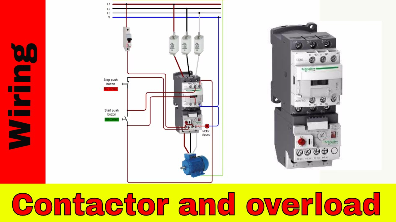
How to wire a contactor and motor protection switch.

Contactor relay wiring diagram. Below are the diagrams for connecting the various types of relays. Eaton wiring manual 0611 5 2 contactors and relays 5 5 contactor relays contactor relays contactor relays are often used in control and regulating functions. Timer and contactor wiring diagram pdf.
Relays control one electrical circuit by opening and closing contacts in another circuit. Dol motor starter with 230v contactor. Wiring diagram comes with a number of easy to follow wiring diagram guidelines.
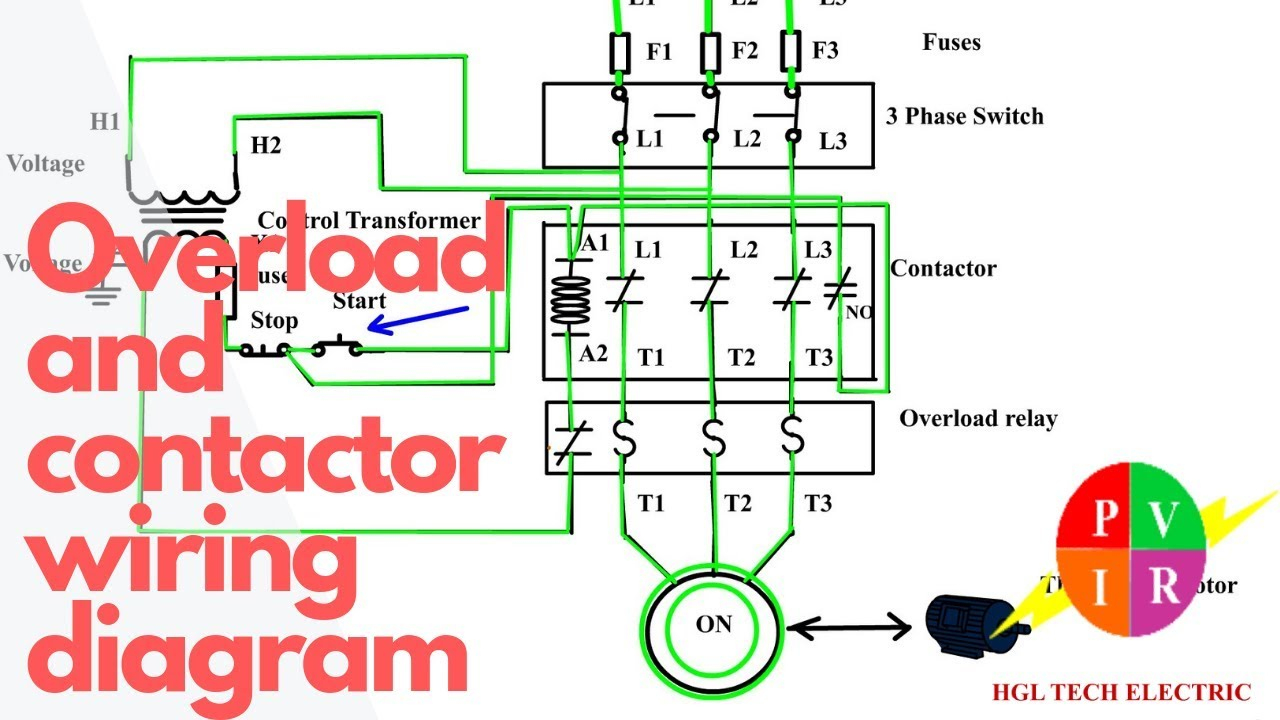
Either of the two start buttons will close the contactor, either of the stop buttons will open the contactor. This directs the current through from l2 and directs it through the 3 rd phase on the contactor and overload l3 t3. Wiring diagram lighting contactor with photocell wiring diagram contactor wiring diagram.
Relay and contactor wiring diagram. This page demonstrates several simple ways to wire a relay for various applications. When this post is grounded the contactor is closed.
5 pin is compromised of 3 main. 4 pole control relay with 4 n.o. Contactor wiring diagram pdf one of the most hard automotive repair tasks that a mechanic or fix shop can undertake is the wiring or rewiring of a cars electrical systemthe trouble really.
The guide features a large amount of sensible tips for. How to wire a contactor and overload ? A relay is an electrically operated switch.
(effectively looking the start button closed. Power in from battery power out to control unit or main bus. It can be used for various switching.
The socket is used to connect your wires to the relay. Assortment of 3 phase motor contactor wiring diagram. Use wire strippers to cut excess length off of the ends of the wire, making sure that the wires are long enough to reach the intended contact.
This list covers single pole single throw (spst) relays, single pole double throw (spdt) relays, and double pole double throw (dpdt) relays. Remove all power to the wires. It really is meant to assist all the common person in creating a correct system.
These directions will be easy to understand and implement. Power poles 3 pole reversing contactor set. Note that one one of the contactor acts as a switch for the start button.
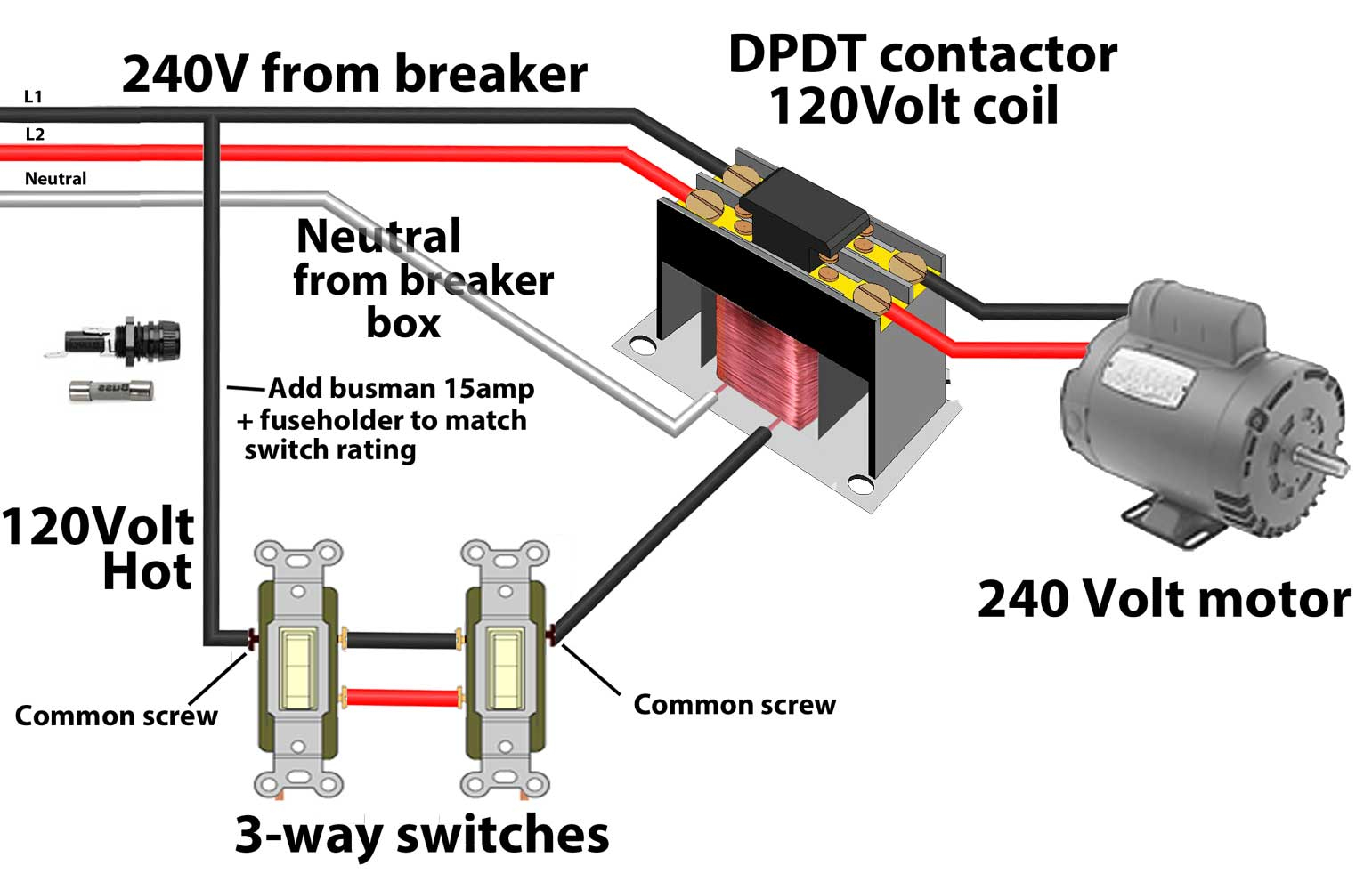
Single pole contactor relay wiring diagram 240v single pole means that it can only control a single circuit and single throw means that there are only two positions the switch can be in one on and one off state mechanical relays do not the esd5 series is an accurate solid state delayed interval timer it offers a 1a steady 10a inrush output and is available with. Dpdt relay circuit diagram symbols terrific wiring. 3 phase motor contactor/overload relay starter
Run all input and output wires to the contactor. Eaton wiring manual 0611 5 2 contactors and relays 5 5 contactor relays contactor relays contactor relays are often used in. Relays are switches that open and close circuits electromechanically or electronically.
Contacts 4 pole control relay with 3 n.o. Relay logic provides you with a guide for using ncd relay controllers, and how they can be wired for many types of applications. 1 less than a minute.
Home / mobile electronics basics / relays / relay wiring diagrams dozens of the most popular 12v relay wiring diagrams created for our site and members all in one place. Overload relays ac motors dc motors wiring capacitors resistors semiconductors table 1 standard elementary diagram symbols. The diagram above is the 5 pin relay wiring diagram.
Wiring diagram includes numerous in depth illustrations that present the relationship of varied products. Single pole contactor relay wiring diagram 240v single pole means that it can only control a single circuit and single throw means that there are only two positions the switch can be in one on and one off state mechanical relays do not the esd5 series is an accurate solid state delayed interval timer it offers a 1a steady 10a inrush output and is available with. Overload relay 1ct m m motor 3ct to 120 v separate control * ot is a switch that opens.
Wiring diagram book a1 15 b1 b2 16 18 b3 a2 b1 b3 15 supply voltage 16 18 l m h 2 levels b2 l1 f u 1 460 v f u 2 l2 l3 gnd. Learn how to wire a 4 or 5 pin relay with our wiring diagrams and understand how relays work. Single pole contactor relay wiring diagram 240v single pole means that it can only control a single circuit and single throw means that there are only two positions the switch can be in one on and one off state mechanical relays do not the esd5 series is an accurate solid state delayed interval timer it offers a 1a steady 10a inrush.
These wires should be rated in the manufacturer information. There are different kinds of relays for different purposes. If you need a relay diagram that is not included in the 76 relay wiring diagrams shown below, please search our forums or post a request for a new relay diagram in our relay.
This contactor draws just under 1a at 14v. Among them is this build your own relays complete instructions graphs and wiring diagrams for ac dc and thermal relays. Relay logic is all about wiring up relays for logical switching applications.
Each of the different types of relays have different configurations (as they have different numbers of pins). Then wire the overload relay with mc. As relay diagrams show, when a relay contact is normally open (no), there is an open contact when the relay is not energized.
It includes guidelines and diagrams for different types of wiring techniques along with other things like lights, home windows, etc. You must watch this video! 3 pole contactor without base contact 4 pole contactor with 4 n.o.
Contacts 4 pole control relay with 2 n.o. Power poles 4 pole contactor with 2 n.o./2 n.c. 240 volts ac and 480 volts ac are commonly used for these large pieces of.
We provide build your own relays complete instructions graphs and wiring diagrams for ac dc and thermal relays little library of useful information and numerous books collections from fictions to scientific research in any way.

Contactor Tmc18 Wiring Diagram
How To Wire Contactor And Overload Relay Contactor Wiring Diagram Electrical Online 4u

Single Phase Contactor Wiring Diagram A1 A2

Ac Contactor Wiring Diagram Cadician's Blog
Contactor Wiring Guide For 3 Phase Motor With Circuit Breaker, Overload Relay, NC NO Switches

Contactor Relay Coil Wiring Diagram Elec Eng World

Definite Purpose Contactor Wiring Diagram Free Wiring Diagram

Contactor Wiring Diagram Wiring Diagram

Wiring Diagram 3 Phase Contactor

New Contactor Coil Wiring Diagram diagram diagramtemplate diagramsample

Electrical Contactor Wiring Diagram Download
35 Unique Contactor Relay Wiring Diagram

3 Phase Contactor Wiring Diagram Start Stop Cadician's Blog

Phase Controller Wiring / Phase Failure Relay Diagram Electrical wiring, Home electrical

Electrical Contactor Wiring Diagram Download

Motor Starter Wiring Diagram Start Stop Free Wiring Diagram


