Alternator Wiring Diagram With Voltage Regulator
The alternator rotor spins inside the windings of the stator. Step #3 remove the 2 wires from the generator, these 2 leads go to the old voltage regulator.
Delco Alternator Wiring Diagram External Regulator
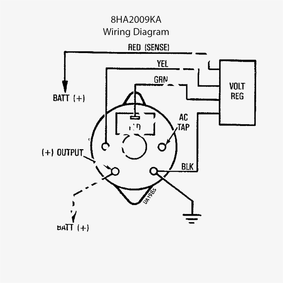
Battery positive cable, voltage sensing wire, and ignition wire.

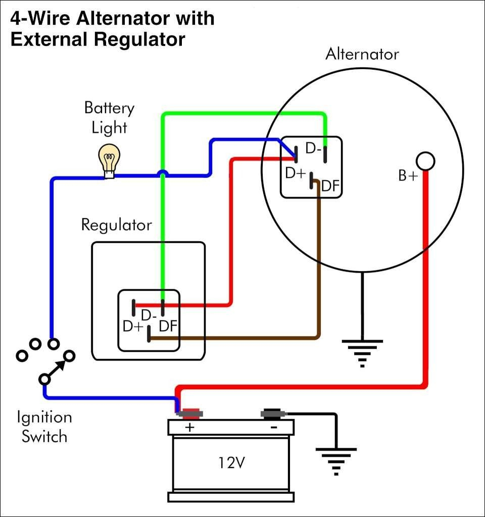
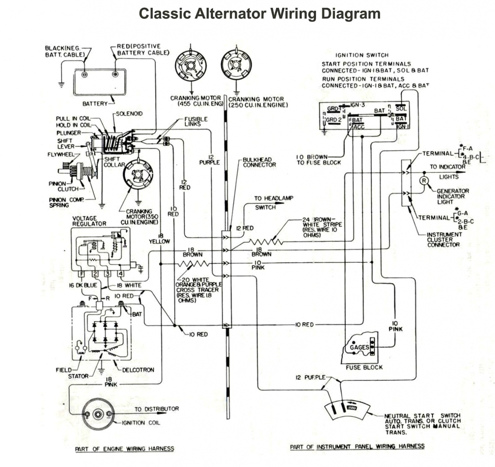
Alternator wiring diagram with voltage regulator. Gm 4 wire alternator wiring diagram. Wiring instructions for the early gm delco remy external regulated alternator. How to wire an external voltage regulator on a gm vehicle.
Wiring diagram for alternator with external regulator wiring diagram is a simplified gratifying pictorial representation of an electrical circuit it shows the components of the circuit as simplified shapes and the gift and signal associates in the midst of the devices. It represents the physical parts of the electrical circuit as geometric forms, with the real power and connection connections in between them as thin sides. Looking for car repair manuals?
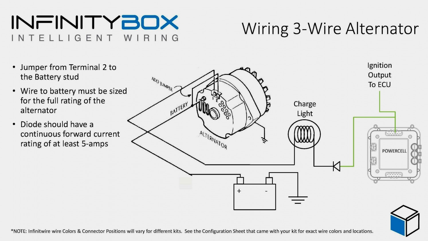
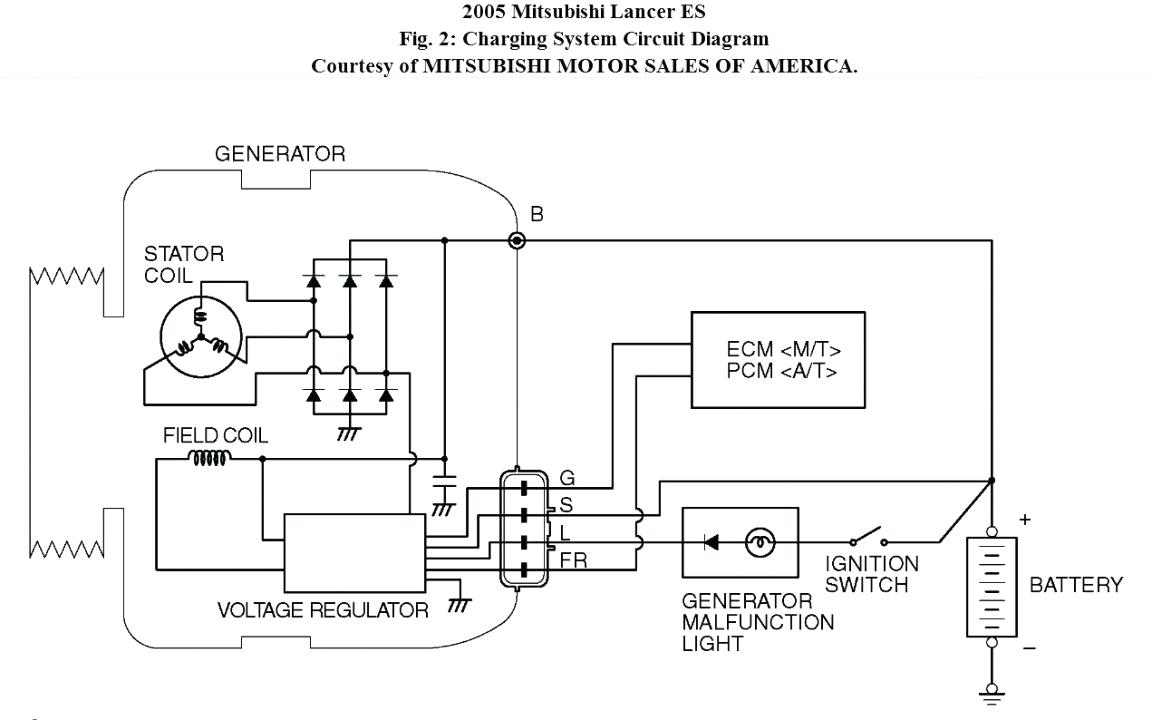
Voltage regulator wiring diagram you will want a comprehensive expert and easy to understand wiring diagram. • ig is the ignition input that turns on the alternator/regulator assembly. Alternator external voltage regulator wiring diagram.
Step #2 locate the voltage regulator, usually on the firewall. Voltage range is 4.8 volts to 5.2 volts and the current rating is 1 amperes.nov 04, 2018 · 04 silverado alternator wiring diagram daily update wiring diagram 1965 mustang voltage regulator wiring diagram; 13 alternator battery charger circuit diagram.
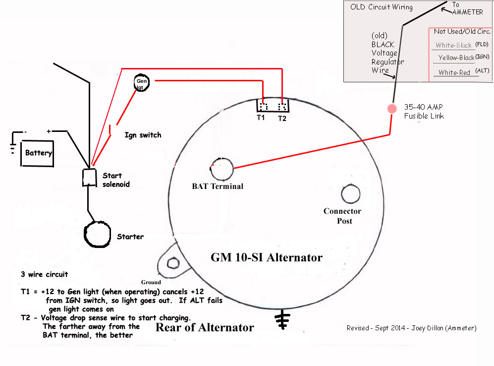
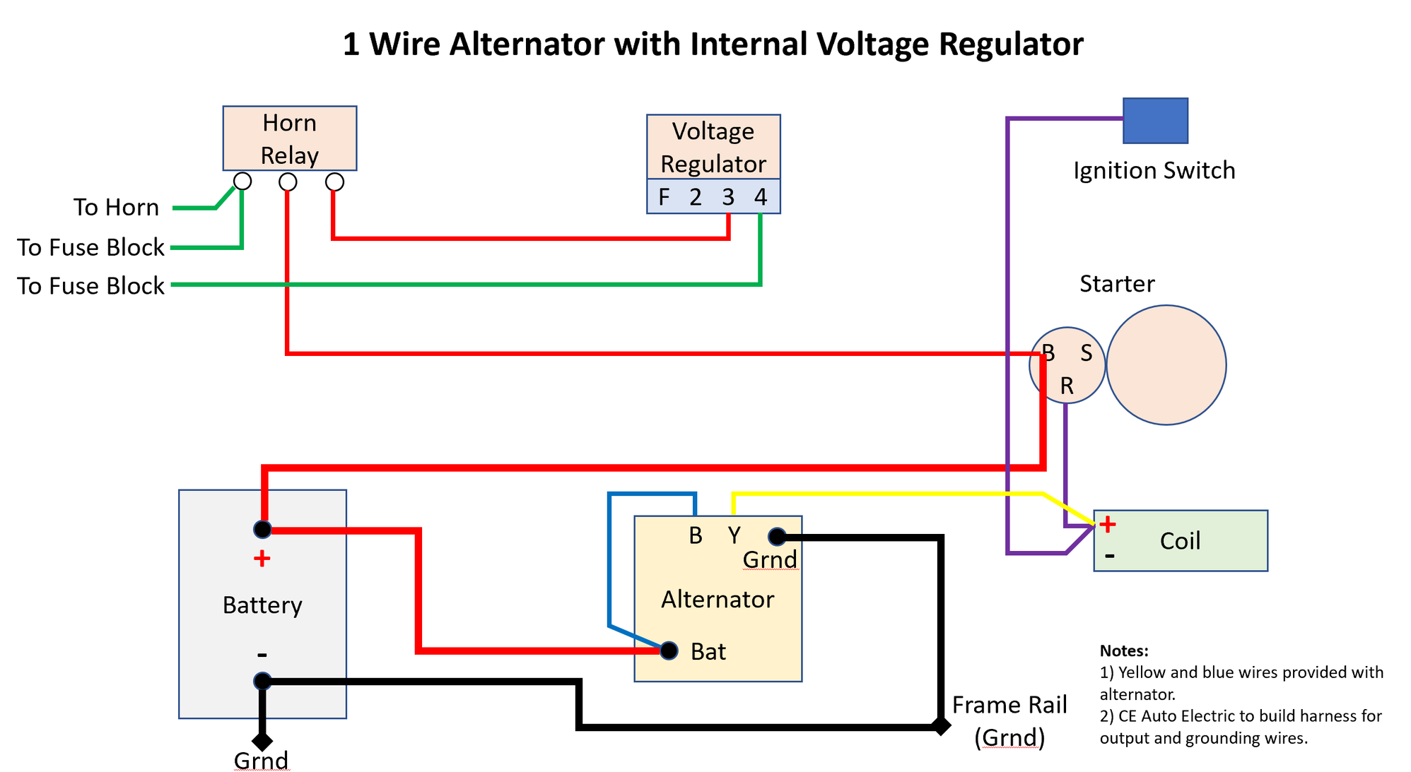
Check the voltage at the bat terminal on the alternator. One of the key differences is how the internal voltage regulator determines charge rate. Since the early '70s gm has built the voltage regulator inside the generator.
If the voltage is 13.5v or more with the engine running, there is a connection problem downstream. It is really simple to draw a wiring diagram; For example , in case a module is powered up and it sends out a new signal of half the voltage in addition to the technician would not know this, he'd think he has a problem.
Amazon affiliate links adjustable dodge voltage regulator. • b is the alternator output wire that supplies current to the battery. To battery generator 2f428 delco remy 12 volt regulator wiring diagram 5 operate generator at 3500 rpm and note.
3 wire alternator wiring diagram source: As the name indicates it regulates the amount of voltage produced from the alternator to ensure a consistent voltage to the battery and electrical equipment in. • s is used by the regulator to monitor charging voltage at the battery.
Wiring instructions for the early gm delco remy external regulated alternator. If not, the structure won’t work as it ought to be. You simply require to have a great comprehension on.
Each part should be placed and connected with different parts in specific manner. The alternator wiring diagrams are below here is a guide to yelp check the connections. Alternator voltage regulator wiring diagram wiring diagram is a simplified tolerable pictorial representation of an electrical circuit.
Additionally, wiring diagram provides you with time frame by which the projects are to become finished. The major difference between wiring a series 6 balmar alternators and a regular alternator which is found often on engines is the charge lamp. Repairing the standard lucas rb106.
The wiring hookup is the same for the cs 130 and cs 130d. You will be in a position to know specifically when the projects should be accomplished, that makes it much easier for you personally to. If the voltage is less than 13.5v, remove the plug connector at the voltage regulator.
To properly read a cabling diagram, one has to learn how the components in the method operate. They did that to make it a quick unit replacement for mechanics who didn't understand how these simple circuits work or how to troubleshoot them. The ignition input wire is attached to the engine.
The fix is to install a podtronics regulator rectifier unit which is close to bullet proof and also fool proof. Regulator voltage setting than the manual specifies is recommended to address battery charging issues. Difference in wiring compared to standard alternators.
A balmar alternator does not need an indication lamp at all to start up, the voltage coming from the ignition switch will be enough (fig 1). Lucas alternator wiring tr online diagramlucas schematic all also diagram ebook rh cv ketipotest. Follow wires and/or use the wiring diagram.
Check the voltage at the bat terminal on the alternator. Step 2 locate the voltage regulator usually on the firewall. If the voltage is less than 135v remove the plug connector at the voltage regulator.
50cc scooter cdi wiring diagram; Wiring diagram figure 2 — n1604 alternator and regulator terminals section a: If not, trace the red wire back to the fuse box, the black wire to its connection at a ground.
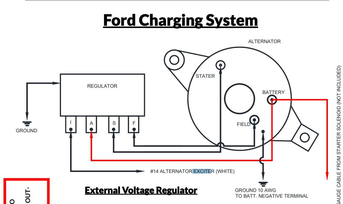
Chevy 4 wire alternator wiring diagram you will need an extensive expert and easy to comprehend wiring diagram. These wires connect to the generator and you don’t need them. Ford alternator regulator wiring diagram effectively read a cabling diagram, one provides to learn how the components inside the method operate.
The easiest way to identify that the alternator is internally or externally regulated is to look in the engine bay for the presence of a voltage. Use a short wire to jump. The circuit comprises three main wires:
With the ignition switch on, check that there is 11.5v minimum between the red wire and the black ground wire to the regulator case. Understanding the alternator • four wires connect the alternator to the rest of the charging system. External regulator 3 wire ford alternator wiring diagram from ls1tech.com.
Wiring Diagram Alternator To Battery Worksheets & Wiring

3Wire Alternator Regulator Diagram Seaboard Marine
Alternator Wiring SI10
78 351m Voltage Regulator Wiring Diagram Wiring Diagram

Single Wire Alternator Chevy Voltage Regulator Circuit Ac

12 Volt Generator Wiring Diagram Download
Chevy 4 Wire Alternator Wiring Diagram Wiring Diagram
Alternator Voltage Regulator Wiring Diagram Collection

voltage regulator diagram Voltage regulator, Alternator

General Electric Voltage Regulator Wiring Diagram

12 Volt Generator Wiring Diagram Download
Gm Alternator Wiring Diagram Internal Regulator Cadician
Gm External Voltage Regulator Wiring Manual EBooks

Mecc Alte Alternator Wiring Diagram Pdf

project car The Mopar Motorhead Page 3
Wiring for alternator with internal regulator

RA60 21RC wiring diagram Voltage Regulator

Ford 302 Alternator Wiring Diagram Database Wiring

Self build adjustable alternator controler Car